Hvac Contactor Wiring Diagram
Note that one one of the contactor acts as a switch for the start button. Posted on aug a tempstar heat should have a wiring diagram on the inside of the door.

Two Pole Contactor Wiring Diagram Wiring Diagram
As stated previous, the lines in a ac condenser wiring diagram represents wires.

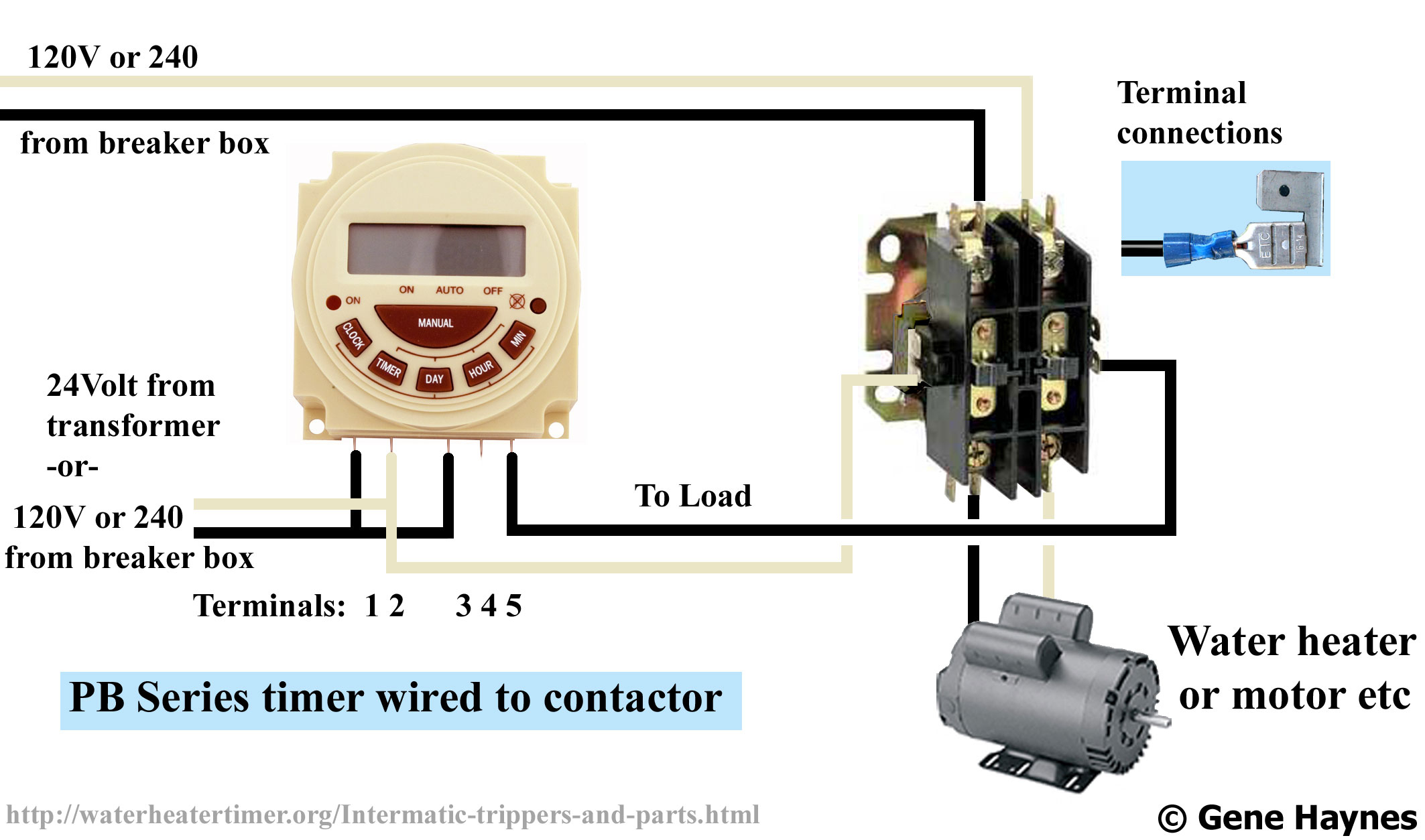
Hvac contactor wiring diagram. 220v ac contactor wiring method and physical wiring diagram brief introduction of contactor if the contactor is divided only from the voltage, there are two types of ac contactor and dc contactor. 1 less than a minute. Timer and contactor wiring diagram pdf.
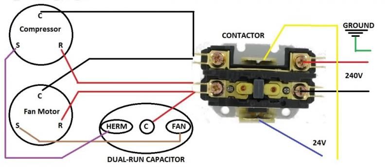
The design of this type of contactor is most advanced among all other types of contactors. Note some ac systems will have a blue wire with a pink stripe in place of the yellow or y wire. This diagram is to be used as reference for the low voltage control wiring of your heating and ac system.
I was tutoring several students with basic wiring this week so i made this video for them to review. Automatic transferred switch (ats) circuit diagram. Always refer to your thermostat or equipment installation guides to verify proper wiring.
If it is divided from the function, purpose, and top, the contactor has vacuum, switching capacitor and other types. Note some ac systems will have a blue wire with a pink stripe in place of the yellow or y wire. Auxiliary contacts each contactor may use one single or one double auxiliary contact block on each side of the base.
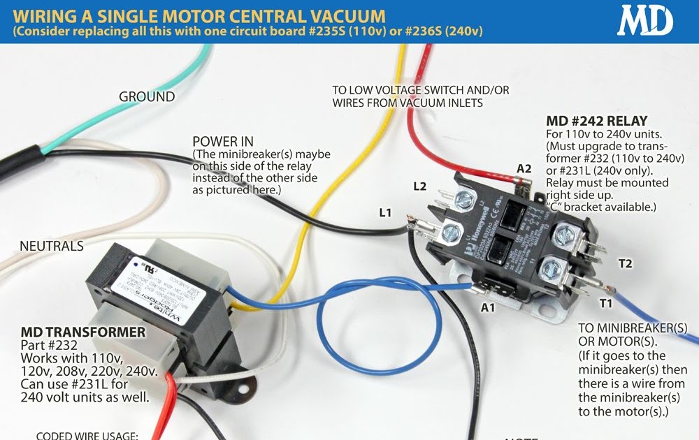
If coil required 110v to 120v then provide 110 volts supply and if it is want 380 volts to 440v to energize then connect same. It includes guidelines and diagrams for different types of wiring techniques along with. Always refer to your thermostat or equipment installation guides to verify proper wiring.
It includes directions and diagrams for different varieties of wiring methods along with other things like lights, home windows, and so forth. Otherwise the arrangement wont function as it. Eaton wiring manual 0611 5 2 contactors and relays 5 5 contactor relays contactor relays contactor relays are.
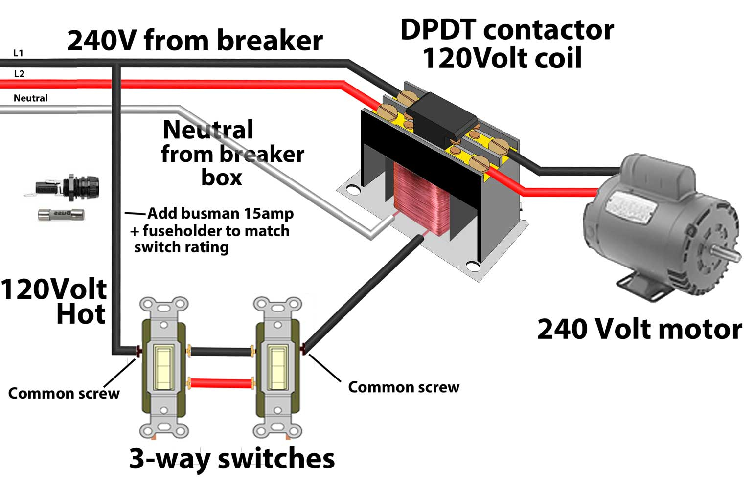
Contactors use 120 volt standard power to energize a magnetic coil, which causes a set of internal contacts to close and provide higher power to the equipment. N4h3 (f series), n4h4 (f series) r4h3, wch3. Either of the two start buttons will close the contactor, either of the stop buttons will open the contactor.
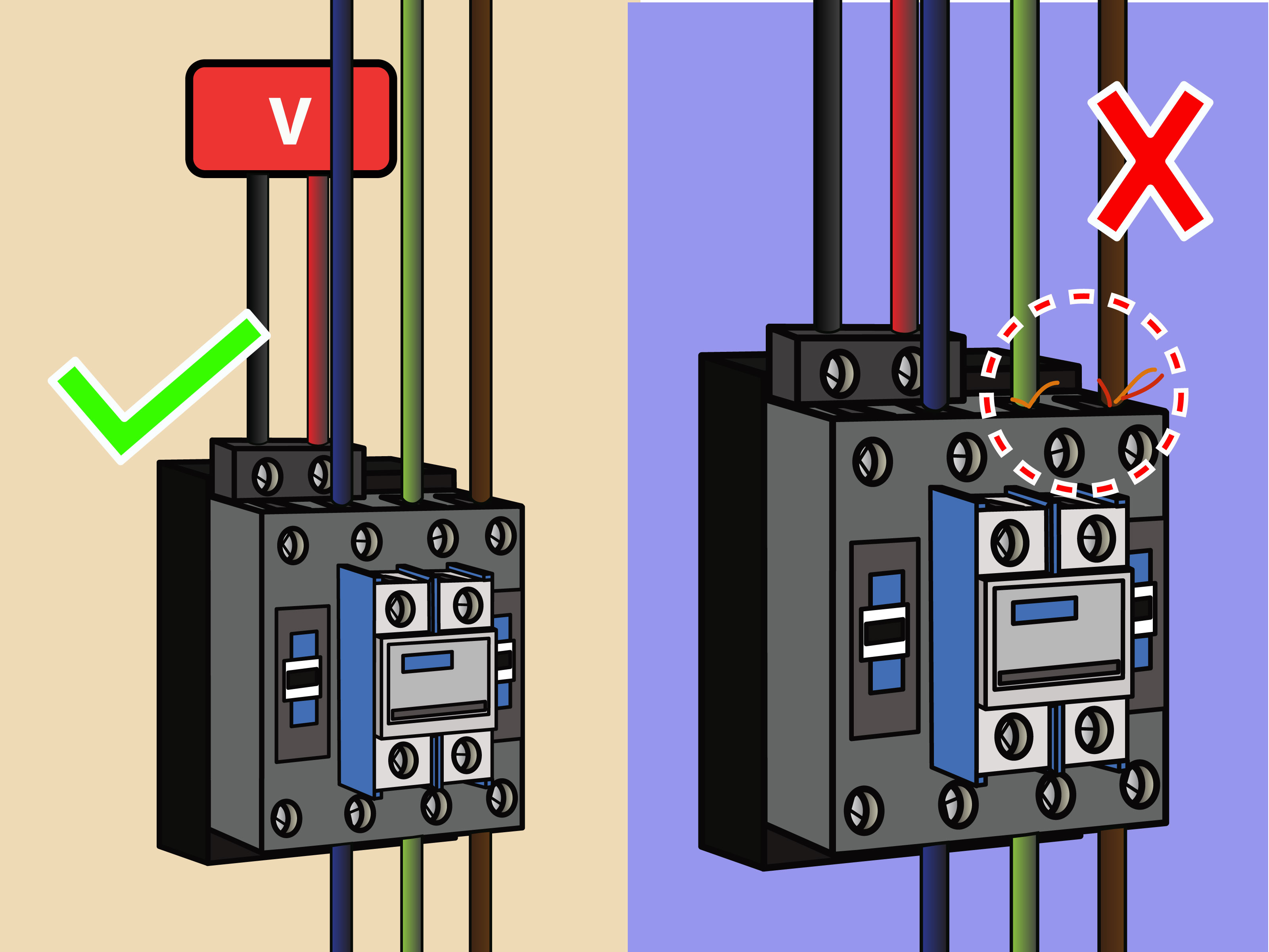
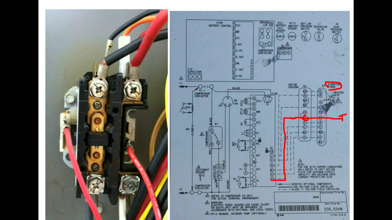
Use these tips to learn how to wire a contactor. Air conditioning ac contactor control board 1 this diagram is to be used as reference for the low voltage control wiring of your heating and ac system. Three phase contactor wiring diagram.
The motor is 3 phase and it appears to be wired according to the diagram for the low voltage 220. Air conditioning ac contactor control board 1 this diagram is to be used as reference for the low voltage control wiring of your heating and ac system. Air conditioning ac contactor control board 1 this diagram is to be used as reference for the low voltage control wiring of your heating and ac.
Wiring diagram book a1 15 b1 b2 16 18 b3 a2 b1 b3 15 supply voltage 16 18 l m h 2 levels b2 l1 f u 1 460 v f u 2. Injunction of two wires is generally indicated by black dot at the junction of two lines. There’ll be principal lines that are represented by l1, l2, l3, and so on.
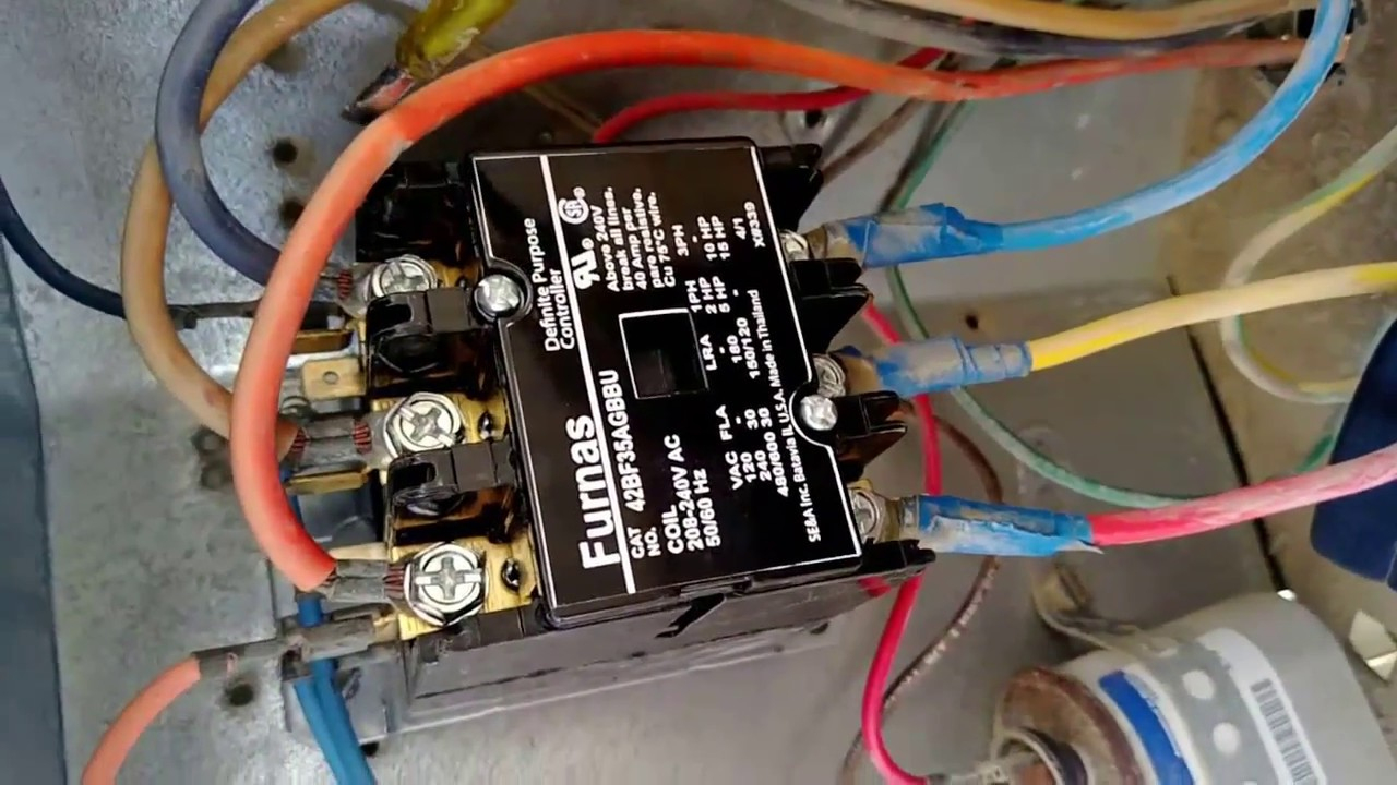
Contactor design and rating contactor nameplate. If you where not in class this may be confusing. How to wire an air conditioner for control 5 wires the diagram below includes the typical control wiring for a conventional central air conditioning systemfurthermore it includes a thermostat a.
Contactor these diagrams are current at the time of publication check the wiring diagram supplied with the motor. Pdf contactor wiring diagram with timer. But, it does not imply connection between the cables.
(effectively looking the start button closed. These voltages must be electrically isolated from the standard 120 volts ac. Wiring diagram book a1 15 b1 b2 16 18 b3 a2 b1 b3 15 supply voltage 16 18 l m h 2 levels b2 l1 f u 1 460 v f u 2 l2 l3 gnd h1 h3 h2 h4 f u 3 x1a f u 4 f u 5 x2a r power on optional x1 x2115 v 230 v h1 h3 h2 h4 optional connection electrostatically shielded transformer.
And ac contactors are widely used in electric power,. Basics 10 480 v pump schematic. A wiring diagram is a simplified traditional pictorial representation of.
Contactor wiring diagram with schematic and diagrams. Sometimes, the wires will cross. 240 volts ac and 480 volts ac are commonly used for these large pieces of.
Collection of contactor wiring diagram pdf. Wiring diagram includes many in depth illustrations that present the connection of assorted items. Contactors are used to provide this isolation.
A wiring diagram is a simplified standard pictorial depiction of an electric circuit. Notesome ac systems will have a blue wire with a pink stripe in place of the yellow or y wire.
Contactors 240 Volt Contactor Wiring Diagram Wiring Diagram

Wiring Diagram 3 Phase Contactor
Ac Contactor Wiring Diagram Cadician's Blog
240 Volt Contactor Wiring Diagram Wiring Diagram

Contactor in 2020 Electrical diagram, Refrigeration and air conditioning, Electronic

Rheem Ac New Contactor Wiring HVAC DIY Chatroom Home Improvement Forum

Hyderabad Institute of Electrical Engineers how to wire a contactor
3 Pole Lighting Contactor Wiring Diagram Today Wiring Diagram Contactor Wiring Diagram
AC Contactor Not Pulling In 10 Reasons Why YouTube Refrigeration and air conditioning

Hvac Contactor Wiring Diagram Wiring Diagram

Hvac Pressor Contactor Wiring Diagram schematic and wiring diagram

Schematic Contactor Wiring Diagram Ac Unit Electrical Wiring

Only the red and wires are connected on the ac unit but the thermostat has all connected. Is
Contactor/Capacitor Wiring Help HVAC DIY Chatroom Home Improvement Forum

Can you show me the proper connections on a Service First contactor CTR 1146 30A, 600V, 24V Coil

Rheem Ac New Contactor Wiring HVAC DIY Chatroom Home Improvement Forum
Air Conditioner Contactor Wiring schematic and wiring diagram
Air Conditioning Contactor Wiring Wiring Diagram Networks

HVAC Training Understanding Schematics Contactors 2 YouTube